
In this part we are going to look at how to load a texture in from an image file and display it on a primitive as well as how to apply custom projection and world matrices to OpenGL rendering.
Step 1: Our Texture2D Class
As you will see in a bit, OpenGL using integers as handles for textures that have been passed to it. Once we have loaded in the data and passed it to OpenGL all we will get back is an integer value that we can use to reference the texture later. This works fine for the most part but I generally like to have a bit more info about each texture when we are creating drawing functions. I also don't like having the ambiguity of whether a integer variable holds a texture or an actual number for something else.
For these reason I generally like to make a Texture2D class to hold the integer as well as a few other pieces of info about the texture. This step is not required but I do recommend following along as it will make your life easier later on and the rest of the series will operate under the assumption that you've created this class.
To get things started go ahead and add another class and Call it Texture2D. Inside the class we will add a few private integers named "id", "width", and "height". We'll then go ahead and add a few some public get accessors for each of these. You should have something similar to the following.
I generally like to keep my local variables camel case while my functions and properties I will Capitalize every word. You don't have to do this but I recommend finding some type of naming conventions that you are comfortable with to make your life easier.
You can also make this class a struct if you so wish. There's not a big difference in the current situation so I'm just going to leave it as a class.
The last thing we need to add is a constructor for the class. It should simply take three inputs, as expected.
With all that in place, our Texture2D class should be ready to go.
Step 2: Adding the Texture to the Project
Before we make the function to load the texture we need to add it to our project. I generally like to make a folder in the project to hold all the game data. I will name this folder "Content".
You can choose any image you wish to text loading. We will be using the System.Drawing Bitmap class to actual load the file so the supported formats are BMP, GIF, EXIF, JPG, PNG and TIFF. I generally like to use png file for sprites since they have transparency, and jpg files for textures. If you don't have an image to test with you can use the one below.
Add it to the Content folder by right clicking on the folder, going to "Add" -> "Existing Item...", browsing to the image file, and selecting add.
Make sure you select "All Files" from the bottom right drop down when trying to find your image.
Once the image is added to the project we need to set a few settings so Visual Studio knows how to handle it. Right click on the image and select "Properties"
This should then open the Properties window.

We need to change the "Build Action" to "None" and "Copy to Output Directory" to "Copy if Newer" or "Copy Always".
This is the process we will be using to add any Content file throughout the series and will not be covered again.
Step 3: Loading the Texture
Now that we've added the texture to our project we can get on with the process of actually loading it in. Since loading in textures is going to be a common functionality for our program I generally like to make it accessible from anywhere inside our namespace.
To do this I like to make a class that will hold a public static function for loading in textures. Again, this is not needed but I recommend doing so since this is how it's going to be set up in this tutorial. So go ahead and add a class, I'm going to call mine "ContentPipe". We also need to add some using statements to the top once it's created.
Now go ahead and create a public static function that returns a Texture2D and accepts a string.
First thing we want to do is load in the texture to a System.Drawing Bitmap class. This is really easy to do since the class handles all of the parsing for us.
Next, before we start getting ready to pass data, we need to tell OpenGL to create a spot for a new texture. We can do this by calling GL.GenTexture which then passes us back our all important id integer. We'll save this in a regular integer for now and create a Texture2D class at the end of the function.
Next we need to let the bitmap class know that we are going to be reading it's data from memory so that it can prepare to be read. The bitmap.LockBits function will do this for us and pass us a BitmapData variable to use.
The last thing we need to do before passing the data is tell OpenGL to bind the texture that we created earlier as the current active texture.
Now we can call GL.TexImage2D to tell OpenGL to create a texture on it's side from the bmpData.scan0 that we pass it. If you want to know more of the specifics about each parameter I recommend reading the documentation about the function in OpenGL.
Now with the transfer done we need to release the bits that we locked earlier.
One last thing we need to do before returning the Texture2D is tell OpenGL how to sample the texture. The two options you will most likely use are either Linear or Nearest. Linear will give you smooth blending between pixels when sprites are scaled up or down. Nearest on the other hand will keep hard edges on each pixel which may be desired if you're going for a low resolution style. For now we will use Linear.
The last thing we need to do is create and pass back an actual Texture2D class. All in all you should have something like the following.
Since our loading function is done all we need to do now is load a texture in our Game class. Simply add a Texture2D variable to the Game class and then call our LoadTexture function from the window_Load function. Make sure that the file path corresponds to your file you added earlier, whatever it may be called.
Step 4: Drawing the Texture
Now that we have the texture loaded and passed we can actually draw it to the screen on a triangle. Before we do that however we need to tell OpenGL to enable textures. This is very easy to do and can be done just after enabling depth testing in the Load function.
And now down in our render function we need to bind the texture BEFORE we call GL.Begin()
Note that at the moment since we've only loaded in one texture it will still be bound from when we called the LoadTexture function so this line is not actually needed. Though this is a very specific case and with any more than one texture you should bind it every time you need to draw it.
And lastly we need to define texture coordinates for each vertex by calling GL.TexCoord2 (very similar to how we used GL.Color3 and Gl.Color4). I'm also going to change the color, position, and code formatting here so if you want the same result you can simply copy over the changes. (You do not need to put TexCoord2 in-line with Vertex2 calls.
One thing to note is that texture coordinates are always between 0 (left/top) and 1 (bottom/right) no matter what size or aspect ratio the image is. This can be nice in some situations but counter-intuitive in others. For example let's say we have a sprite sheet of images that are 32px by 32px each 8 columns wide and 2 rows tall. If you were to try and find the appropriate texture coordinates for a particular cell in that sheet you would have a hard time unless you knew the size of the image. This is the kind of scenario where having a Texture2D class that keeps the image width and height values bundled together comes in handy.
Regardless, if you've copied the lines above you should have something that looks like this.
I highly recommend experimenting with this new functionality with different images and texture coordinates. Maybe even try taking a sprite sheet and choosing your texture coordinates based on a variable that changes over time to create animation.
Step 5: Matrices in OpenGL
Now that we have images being displayed on the screen we can shift gears a bit. This step wasn't long enough to be it's own part so I decided to just combine it with this one.
First things first, if you have not heard of matrices before I do recommend going and learning about how they are used in computing and 3D rendering specifically since I won't be getting into a lot of the specifics here. Regardless, if you are oblivious you should still be able to follow along and get a general understanding of how to use them since OpenTK's Matrix classes do most the heavy lifting for us.
If you've been following along up to this point you might have realized that the texture coordinates for the scree go from (-1, 1) in the top left to (1, -1) in the bottom right. This is default coordinate system in OpenGL because this is desirable when you are setting up a perspective view in 3D space. However since we have been working with 2D sprites and triangles up to this point this might be a bit counter-intuitive.
So let's change that. I first started programming in XNA and the default there was (0, 0) being the top left of the screen and (screenWidth, screenHeight) being the bottom right. This meant that every 1 step in the x or y direction meant one pixel difference on the screen. This also common in many other 2D platforms but if you have some preference towards a different set up then by all means go with that.
In order to get the desired effect we are going to be creating a projection matrix that defines the transformations for creating a orthogonal view. This is really easy to do in OpenTK because the Matrix4 class already has a function that does this for us.
Note the last two numbers define the "near" and "far" clipping planes. These are essentially what define the min and max values for z and can affect the depth buffer accuracy when these are too far apart. This will become more important later when we are dealing with 3D perspective views.
Once that matrix has been created we need to pass it to OpenGL before we start rendering. To do this we simply tell OpenGL which type of matrix we are working with GL.MatrixMode and then pass it over with GL.LoadMatrix.
If you run the game now you might think you've done something wrong since nothing will show up. What's actually happening however is our coordinates for our triangles where only spanning a change of 1 on both the x and y axis and therefore in this new coordinate system only span 1 pixel. Let's change that.
Running this will produce a result like so.
Now that we have our projection matrix set up like we want we can also mess with what is called the "ModelView" matrix. (also sometimes called the "World" matrix) This matrix is designed to contain transformations that take place before the projection matrix is applied. Essentially what we want to use it for is to define how a primitive is moved, rotated, and scaled. This can have many uses in 2D and far more in 3D but for now we will look at how it can be used to enable you to draw multiple penguins in various places with only one function.
So to get started let's move our most our drawing code into a function called DrawPenguin.
Now let's make a new Matrix to hold our transformations and initialize it by combining Matrix4.CreateScale, Matrix4.CreateRotationZ, and Matrix4.CreateTranslation.
The general rule of thumb when it comes to matrix transformation is always multipy scale * rotation * translation. This will keep the resulting matrix from deforming your object in unexpected ways.
Then let's change the matrix mode and load the new matrix in like before.
And finally we'll call DrawPenguin.
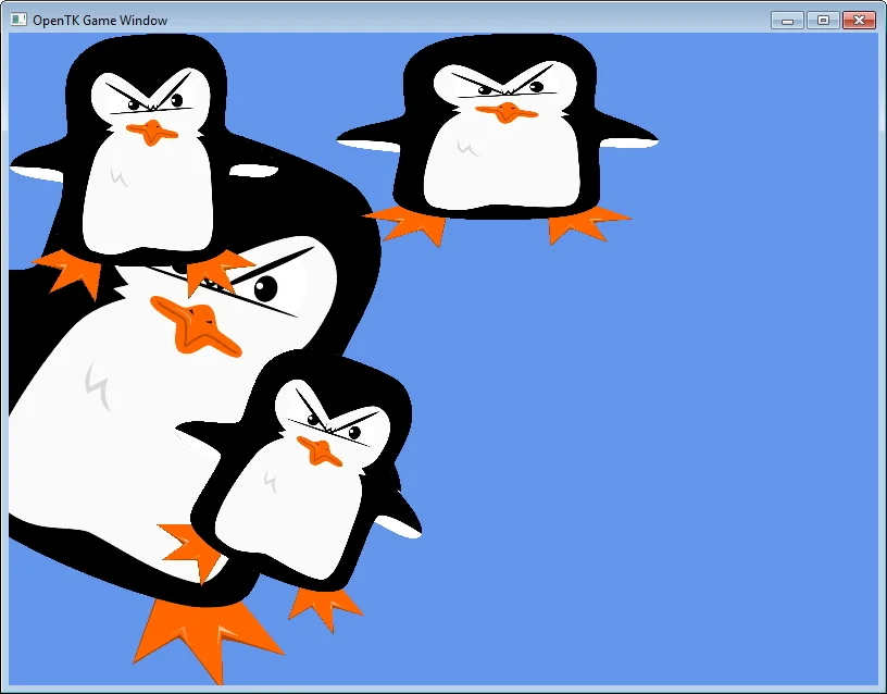
We can then copy and paste these lines a couple times, changing the transformation values for each one, and end up with something like this.
Now as you can see the only Vertices we've passed to OpenGL are the ones in DrawPenguin but if we run this now we will actually see 6 triangles (2 for each penguin) in vastly different positions. This may seem fairly pointless now, but later on when we start dealing with 3D models it will become apparent just how useful this kind of functionality is.
Now as you've probably noticed we have a slight problem with the penguin in the back. This is a similar problem to the alpha blending we had before but unlike that one this one can actually be solved.... kinda.
Our problem again is that our penguin in the back is being draw last but is being drawn behind the other penguins and they, as you might remember, are actually made of 2 triangles creating a rectangle. OpenGL does not care what is in the texture when doing it's depth buffer writing so even though the pixels around the penguin are completely transparent it still writes the corresponding z value to the depth buffer.
This can be remedies fairly easily by enabling what is called "Alpha Testing". So back in our Load function lets add another call the GL.Enable and then set the corresponding alpha testing function.
This function essentially says to only write to the depth buffer if the alpha value of the current texture is greater than or equal to 0.5f. Now in this case a value of 0.5f (half-transparent) is fine since our sprite has fairly hard edges. However you may need to change this for future applications. Essentially you have a trade off here. A higher value will cull much more of the semi-transparent pixels of the image which will decrease what I like to call "crummy edges" but will also decrease how smooth the image looks at the edges. A lower value will increase the "crummy edges" but will also increase the anti-aliasing effect on the diagonal edges.
Here's a side-by-side comparison of the two extremes.
Whichever value you prefer once you've got all this in place you should have something like the following output.
That about wraps up this tutorial. If you want to continue learning more about OpenTK make sure you continue to the next part where we will be learning about how to get Keyboard and Joystick input in OpenTK.